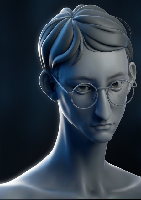
Definition
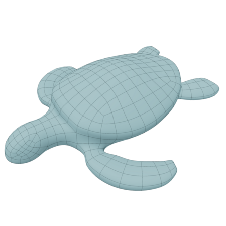
Topology in 3D graphics reflects the arrangement and structure of vertices, edges, and faces that compose a 3D model, defining the placement and interconnection of polygons.
Good topology is crucial for achieving clean, efficient, and deformable models, especially in animation, games, and simulations. A well-constructed model features evenly distributed polygons, smooth surface transitions, and edge flow that complements the model’s form and intended movements.
Topology is not about how an object looks on the outside, but about how it is structured internally—what elements it comprises and the order in which they are connected. Two objects might look identical at first glance, but one will possess clean topology (easy to animate, easy to smooth, easy to edit), while the other might contain triangles and n-gons in problematic places that will cause issues at the first attempt to modify or animate anything.
Topological Elements and Their Significance
Topology is not dictated by a single rule, but rather by a collection of interconnected elements—polygon types, loops, poles, flow direction, and the overall mesh structure. Each of these elements influences how the model behaves during smoothing, deformation, and animation. Examining these elements individually helps in understanding why the same shape can be modeled in dozens of different ways, yet only some of those methods will be technically correct and practical for further work. Next, we will explore each element in detail—from basic polygon types to more complex concepts such as poles and mesh flow.
Polygons
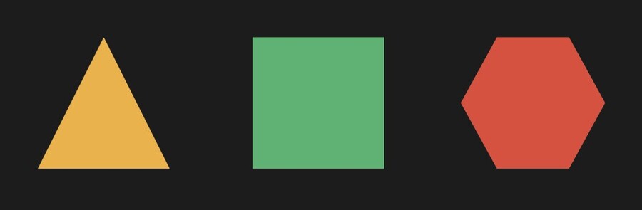
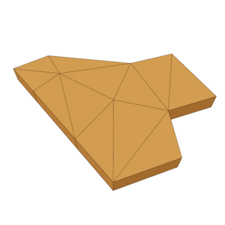
Triangular PolygonsA polygon with three sides or faces is called a triangular polygon. It should be noted that triangular polygons can cause issues when subdividing or smoothing geometry, as well as in cases of mesh deformation or animation.However, triangles are not inherently bad: they always remain flat regardless of their position in space, which makes them ideal for final rendering—this is why any quad or n-gon is automatically broken down into triangles by the engine before being displayed on screen.
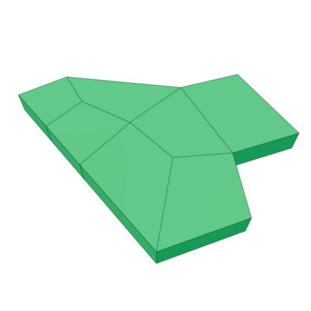
Quadrilateral PolygonsFour sides or facets form a quadrilateral. The quadrilateral polygon method is preferred when modeling or animating an object.Quadrilaterals are predictably divided, making them ideal for smooth surfaces. They deform better during animation (for example, facial rigs, muscle movement).
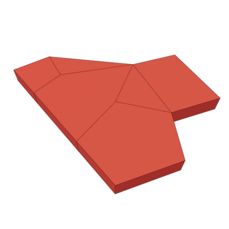
N-gonsA polygon is classified as an N-gon if it has five or more sides. N-gons are known to cause rendering issues—particularly during texturing and deformation for animation—so designers usually try to avoid them.
Rib loops and polygon loops
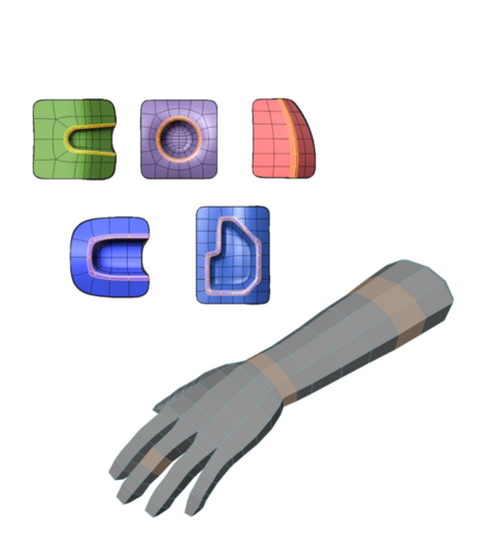
A ring or loop of edges, or edge loop, is a closed sequence of edges. A ring or loop of polygons, or faceloop, is a closed sequence of polygons.
For organic models (people or creatures), the edge loops must mimic the movement of muscles and joints (for example, around the eyes, mouth, elbows, or knees).
For models with hard surfaces (vehicles, machinery), the contour lines of the loops should replicate mechanical seams and sharp edges.
Understanding the edge loop is one of the key skills in modeling because properly placed loops determine whether a model will bend smoothly during animation or break at sharp corners. In Maya, you can easily select loops by double-clicking an edge (Maya will automatically select the entire closed chain), or you can use Select → Edge Loop Tool for more flexible selection control.
Poles
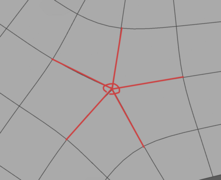
E-pole — poles composed of five edges intersecting at a single vertex.N-pole — poles composed of three edges also intersecting at a single vertex.Poles are elements of a mesh drawing that are not errors. They can often be found where one shape «joins» another.
First finding: it is preferable to work with quadrilaterals.
Flow
If the flow contradicts the details, it creates undesirable artifacts. The flow can be directed using poles, which are vertices with three or more connections. Poles are points where adjacent loops can branch off and move in different directions.By arranging the poles correctly, we can ensure that our loops follow the contours of the details we wish to separate or highlight.Put simply, flow is the direction in which the edges and loops «flow» across the surface of the model. A good flow follows the object’s shape—it wraps around curves, emphasizes edges and seams, and does not chop the detail chaotically across. A poor flow creates visual noise—edges run haphazardly, causing even technically correct topology (free of n-gons and excess triangles) to look messy and to smooth poorly in desired areas.
Uniform geometry vs. Non-uniform geometry
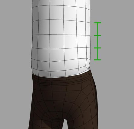
Uniform geometry refers to geometry possessing the property of homogeneity. All the angles and faces of the object are congruent (identical in shape and size). The structure appears the same from any vertex, face, or edge.Simply put: no matter where you look, the object will appear uniform. A good example is a regular sphere or a cube with evenly distributed segments: every face repeats the neighboring ones in shape and size, without abrupt changes in density.
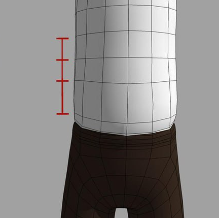
Non-uniform geometry is geometry lacking the property of uniformity. The object’s elements (angles, faces, edges) have different shapes and sizes. The structure looks different when observed from various viewpoints.Simply put: the object has an irregular, variable, and complex form. Most real-world objects you will model in the course—houses, props, furniture—are non-uniform by nature because different parts require varying polygon density: more detail is needed where precision is required (joints, corners), and less is needed on flat, uniform surfaces.
Planar vs. Non-Planar
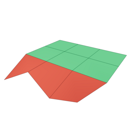
Planar surfaces are perfectly flat, with all vertices lying in a single plane.Non-planar surfaces contain curved polygons whose vertices
do not lie in a single plane, which often leads
to rendering artifacts and export issues.
In practice, non-planar faces are a frequent hidden issue: an object might appear normal in the viewport, but when rendered or exported to other software, strange shadows, fractures, or holes can appear on such faces. You can check a face’s planarity either by manually aligning its vertices onto a single plane or by using specialized tools designed to detect non-planar polygons. Maya includes a built-in tool for this—there is no need to search for a third-party plugin.Mesh → Cleanup opens a dialog where you can enable the Non-Planar Faces option under Fix by Tessellation. The tool will highlight all non-flat faces in the model, and you can even configure automatic correction through triangulation.Display → Polygons → Non-Planar Faces is a lighter method to simply visually flag non-planar faces directly in the viewport with color, without running a full geometry cleanup. You can then fix them manually.
Convex VS Concave
This distinction is important to consider when building the form: convex surfaces (sphere, dome) are usually simpler to model and smooth, whereas concave sections (recesses, niches, inner corners) require more careful control of the topology to avoid self-intersections or distortion during smoothing.
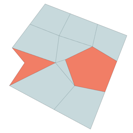
Convex
Relating to surfaces that curve outward.Concave
Relating to surfaces that curve inward.
Non-manifold geometry
Non-manifold geometry refers to a three-dimensional shape that cannot be unfolded into a two-dimensional surface. Problems arise in areas where the geometry behaves ambiguously—for instance, where more than two faces meet at a single point, or where several surfaces are connected by only an edge or a vertex.